Triangulation
Navigating the threshold dialog
![]()
To get to the thresholding dialog click on the button “Preview Threshold Selection”.
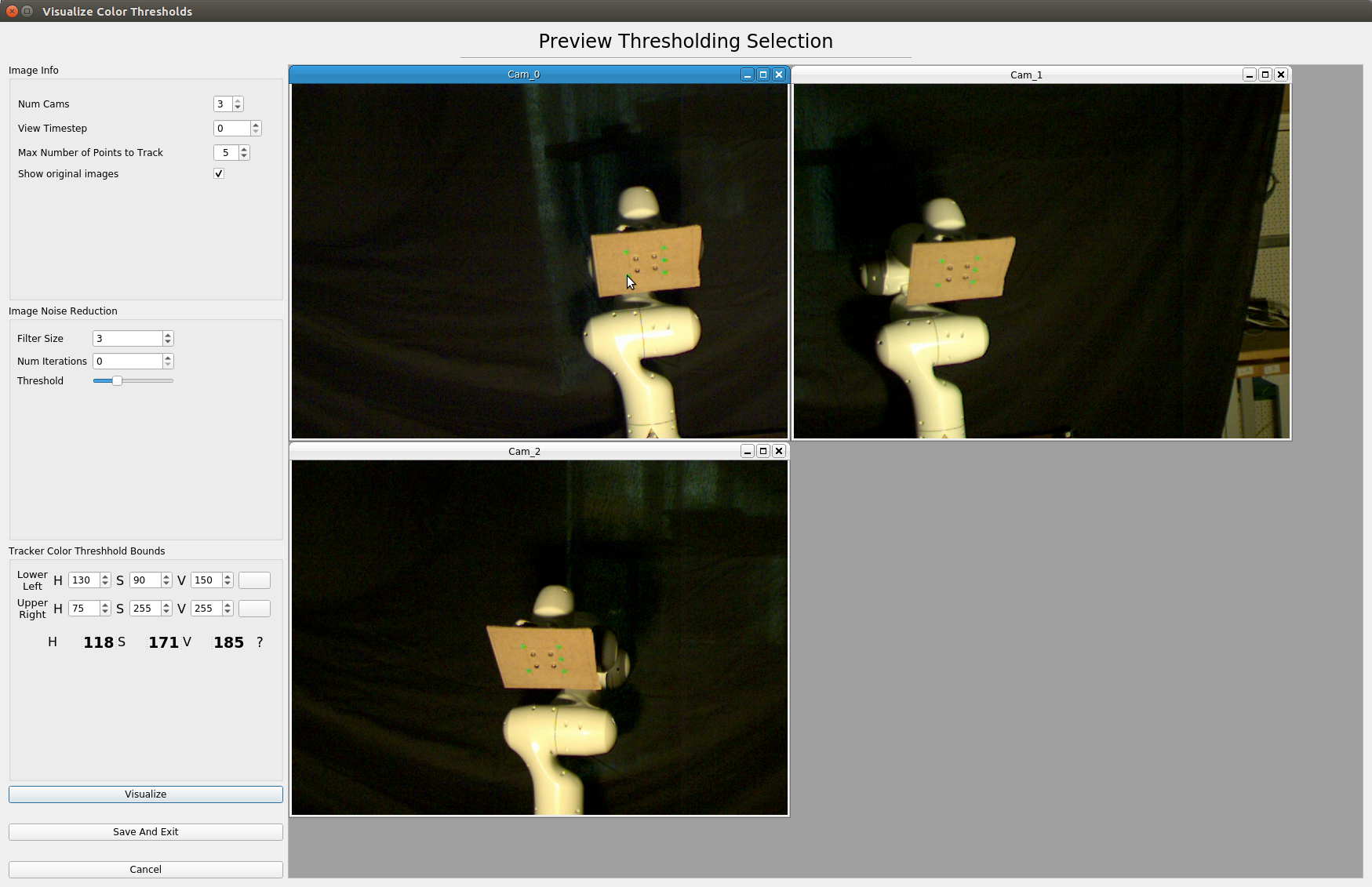
Once in the thresholding dialog you will see the first timestep of images for all cameras. If you uncheck the box labeled “Show Original Images”, you should see black images now in place of the original images you saw before. This is normal as you haven’t set your colors for the algorithm to threshold against.
Choosing the Color to threshold
This can be a confusing task for first time users as the interface is a little unintuitive. There are two buttons in the “Color Threshold Bounds” panel. One is labeled “Lower Left” and the other “Upper Right”. These names will make more sense in a bit.
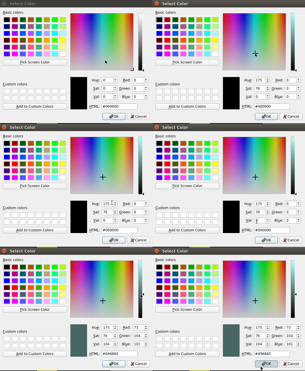
Click the button for “Lower Left” it will bring up a color dialog where you need to select 3 values. There algorithm thresholds colors based on the HSV (Hue, Saturation, Value) color scale. A rough way of thinking about this is that hue is the color in which we are interested, saturation is how rich that color is, and value is the brightness of the color.
As you can see in the GIF, there is a square with colors and a slider to the right of it. The square has Hue on the horizontal axis and saturation on the vertical axis. The slider is concerned with Value.
We want to select a bright green color range as that is the range for our example colored markers. We select the left and bottom bounds for our Hue, Saturation, and Value. Then click Ok.
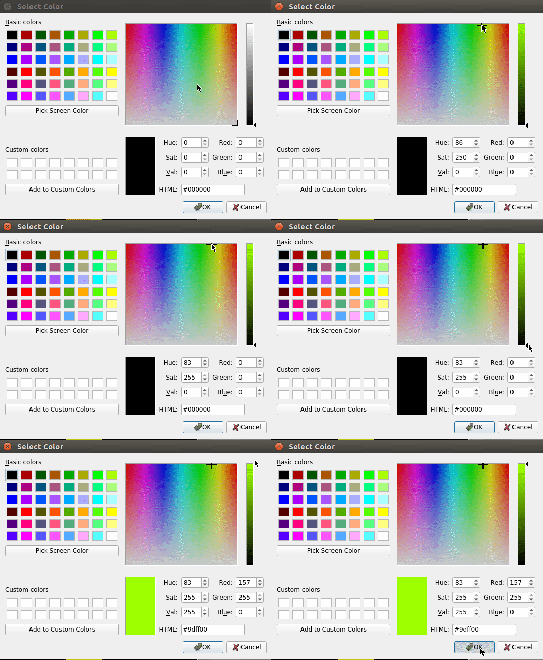
Repeat what we did above, except this time choose the right and upper bounds for our color thresholding.
This task is confusing, I know. Look at the image below to get a better feel for what we are trying to accomplish.
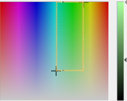
The orange dotted line square in the image is the imaginary area of the Hue/Saturation space that we would like to use. The black cross in the lower left is the marker we place for the Hue/Saturation in the “Lower Left” color dialog. The black cross in the upper right of the image is the marker we placed for the Hue/Saturation in the “Upper Right” dialog.
Looking to the slider, we see the triangle on the bottom is from our Value placement in the “Lower Left” color dialog. Consequently, the upper triangle is from the “Upper Right” dialog. This forms a range for the Value of our thresholding.
Once you get your color threshold range set, uncheck the box labeled “Show Original Images” to see how well your markers were thresholded against those contraints. If your thresholded image isn’t correct, you need to make adjustments to the range you provided, or use some of the filtering and further fine-tuning helpers in the “Image Noise Reduction” panel. Check out the section on bad results below for more tips.
What should the thresholding look like at the end
Good Result
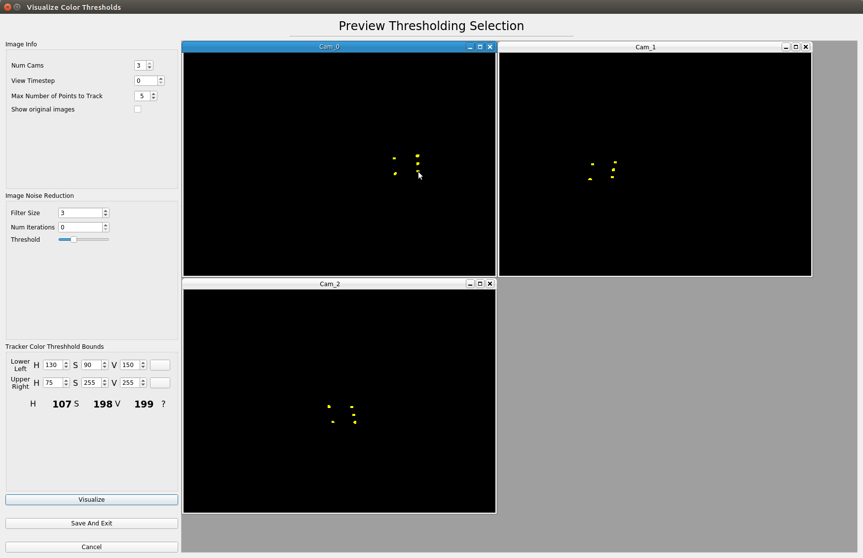
If all goes well, you should see a nice thresholding of your tracking markers. If, it doesn’t look so good, you need to figure out what is messing up the thresholding.
Now that you have this one good timestep, go through as many of the subsequent timesteps to make sure that the ranges you selected also work there. Most times small adjustments need to be made to account for things like small differences in light or reflection in the timestep’s image.
Bad Result
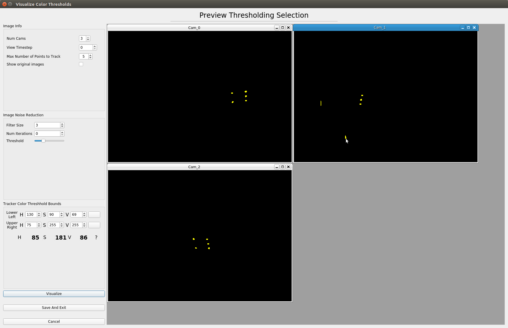
If your thresholded images look similar to this, then it helps to click on the yellow parts that are not correct and see what their colors are. These colors show up in the lower left corner of the dialog. Perhaps your range of colors is too large. Using the image noise reduction options can help as well.
It is often the case the one or two cameras don’t have a good view of the motion or there are too many artifacts in those images. For triangulation we need a minimum of two cameras. You can drop cameras from the triangulation if they don’t have good thresholding. This is described more in the next section.
Running the triangulation
When you are happy with how your color limits work for your images across timesteps, save the settings from the threshold dialog to return back to the triangulation dialog.
If you are not happy with using some of the cameras for the calibration, you can de-select them here. Make sure you update the “Min number of cameras that see point” value to reflect this change. Otherwise, the triangulation will fail. This failure happens because the triangulation algorithm looks for a timestep where this number of cameras can all see all of the points. If this number is higher than the number of cameras checked, then it won’t find a useable timestep.
The option to require fewer cameras to see the point than the number of cameras checked is a valid option. However, because of the optimization algorithm used to make sure the epipolar lines from each camera intersect, there will be different values if two or three cameras are used.
With all of that aside, you are ready to start the triangulation!
Click “Start!”
Output
During triangulation there are lots of text and info printed out to the terminal from which SnakeStrike is running. Looking at this info can be helpful diagnosing things if an error occurs. Furthermore, it is useful to watch this output as the error of the optimal correction for the intersection of epipolar lines for each timestep is written here. If you see large error values it can be indicative of problems with the triangulation.
Marking the initial starting points
After you are happy with your selection of bounds, noise filtering, and cameras to use, click the “Start!” button to begin the triangulation of points. In the middle of this process you will be prompted by a dialog that looks like the following:
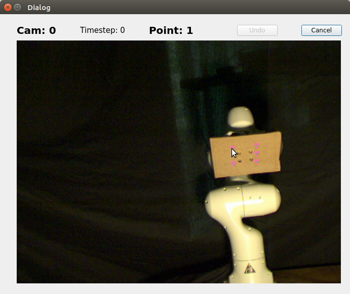
Your job is to click the corresponding points for each camera. Don’t worry, if you make a mistake, you can undo them. A single click is all that is needed to mark the listed point for the listed camera. It makes sense to have a logical ordering of the marking of the points as they will be intersected by a line in the triangulation viewer.
For example, when working with a snake, I like to start at the head and go along the body towards the tail this makes it easy for me to visualize the body form of the snake when I am looking at the 3D points later in the viewer.
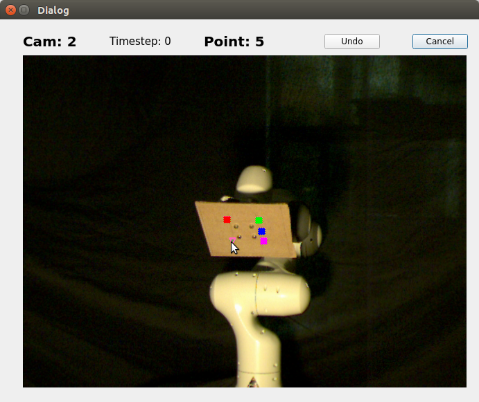
You don’t need to be super accurate when selecting the points in the dialog, the point closest to the pixel that you click will be selected. Furthermore, as you can see in the image above, points that have already been chosen are covered up by a colored square. This coloring is the same across all cameras so that you can visually make sure that the points you clicked are being saved as you intended.
Ok, I think I did the triangulation well, let’s see how it looks.