Calibrating cameras
Camera Setup
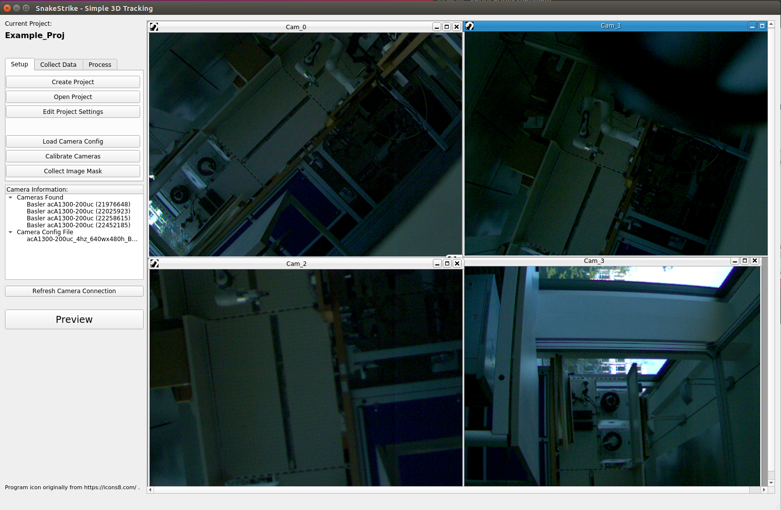
The “load camera config” button allows users to load camera configuration files that follow the GenApi standard. Most cameras sold today should comply with this standard for configuration. If the camera being used does not comply to this standard, it can still be used, but it will have to be configured by a 3rd party program and one will most likely need to exit and restart SnakeStrike whenever the configuration changes.
In my setups I use Basler acA1300-200uc USB 3.0 cameras. These cameras, and all Basler cameras, follow the GenApi standard. Furthermore, Basler provides a GUI utility for creating the calibration files for the cameras. This utility is called PylonViewerApp and is already installed in the docker image. One can set up a camera to the needed configuration and then save the configuration as a separate file. This .pfs file is in accordance with the GenApi standard and is then easily loaded into SnakeStrike.
Camera Fine-tuning
Camera images that are in focus and well lit are needed for calibration to function well. As the focal length and depth of focus are inherently dependent on the cameras used, it is important to have something to use to help make sure the camera is properly focused.
One technique I have used to focus cameras is to have a small tape measure at the height I expect my capture object/subject to be at during capture. In the case of a very dynamic movement the tape can be extended with supports to cover the area I expect the subject to be in during movement.
The tape measure is helpful for focusing as the small writing on it are easy to use to tell if the camera is in focus. Depending on how far the cameras are from the computer used in the setup, this step might need to be done with the help of another person.
Lighting
Since you are using a lower camera speed to do the calibration than you will be using during actual captures, the cycle rate of the lights you are using to light up the experiment space can be lower. The calibration algorithm expects a fairly well lit calibration image in each camera’s timestep image. If the light is not sufficient the algorithm will not find large numbers of matching points.
Calibration Object
The calibration routine that is used was originally developed by Li, B. and Heng, L. and Köser, K. and Pollefeys, M. in 2013. The algorithm is able to calibrate cameras as long as the calibration image is flat and the cameras are able to see a portion of the calibration image. It is not necessary that all cameras see the calibration image in the same timestep as long as the cameras can link across timesteps.
For example, if camera A and camera B can see portions of the calibration image in timestep 1, but not camera C. Then in a later timestep camera C and either camera A or camera B, or both, must see portions of the calibration image together. It could be the case that the several of these timesteps are needed.
For example, if there are 20 calibration images taken in total and in 18 of those images camera A and camera B can see the calibration image while camera C cannot, then even though camera B and camera C can see portions of the calibration image together for the other 2 calibration images, it might not be enough to calibrate the cameras’ extrinsic matrices with low error.
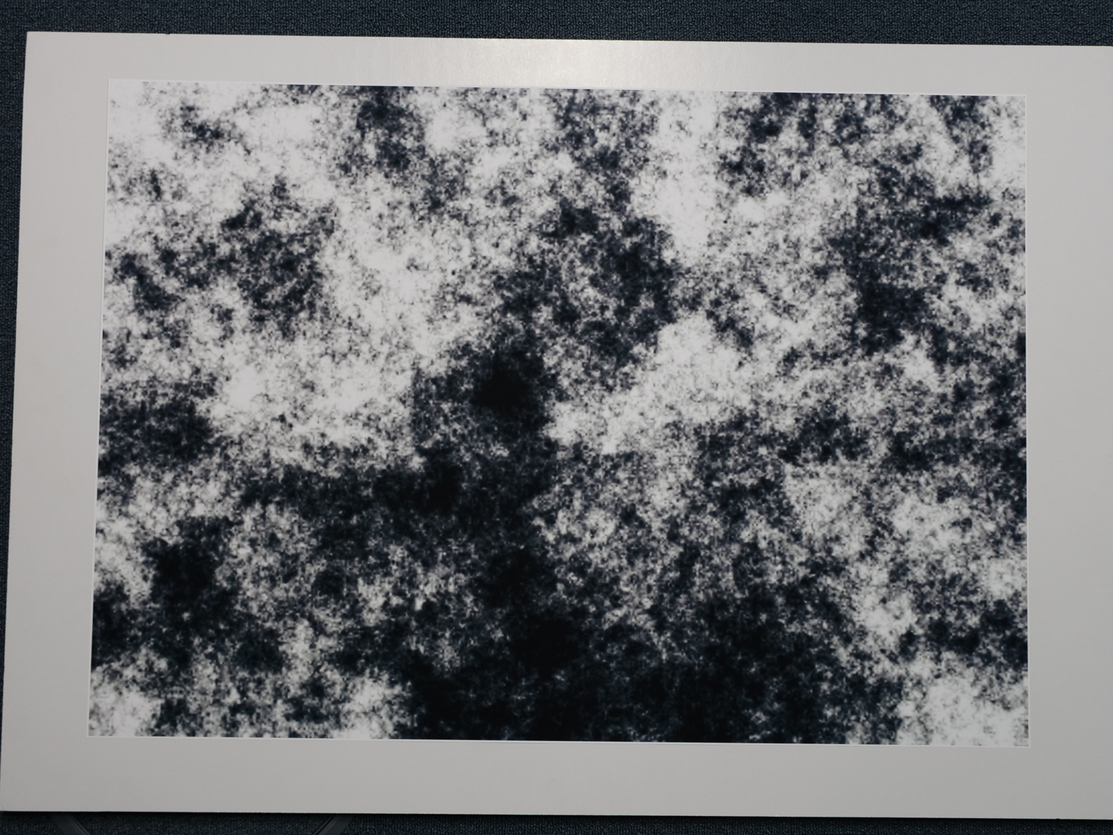
The algorithm requires the use of a new type of calibration image.
This specific image is located in every project directory under “proj directory”/calib/default_calibration_pattern.png . This file can be re-generated using code already installed into the docker environment.
Mounting the image
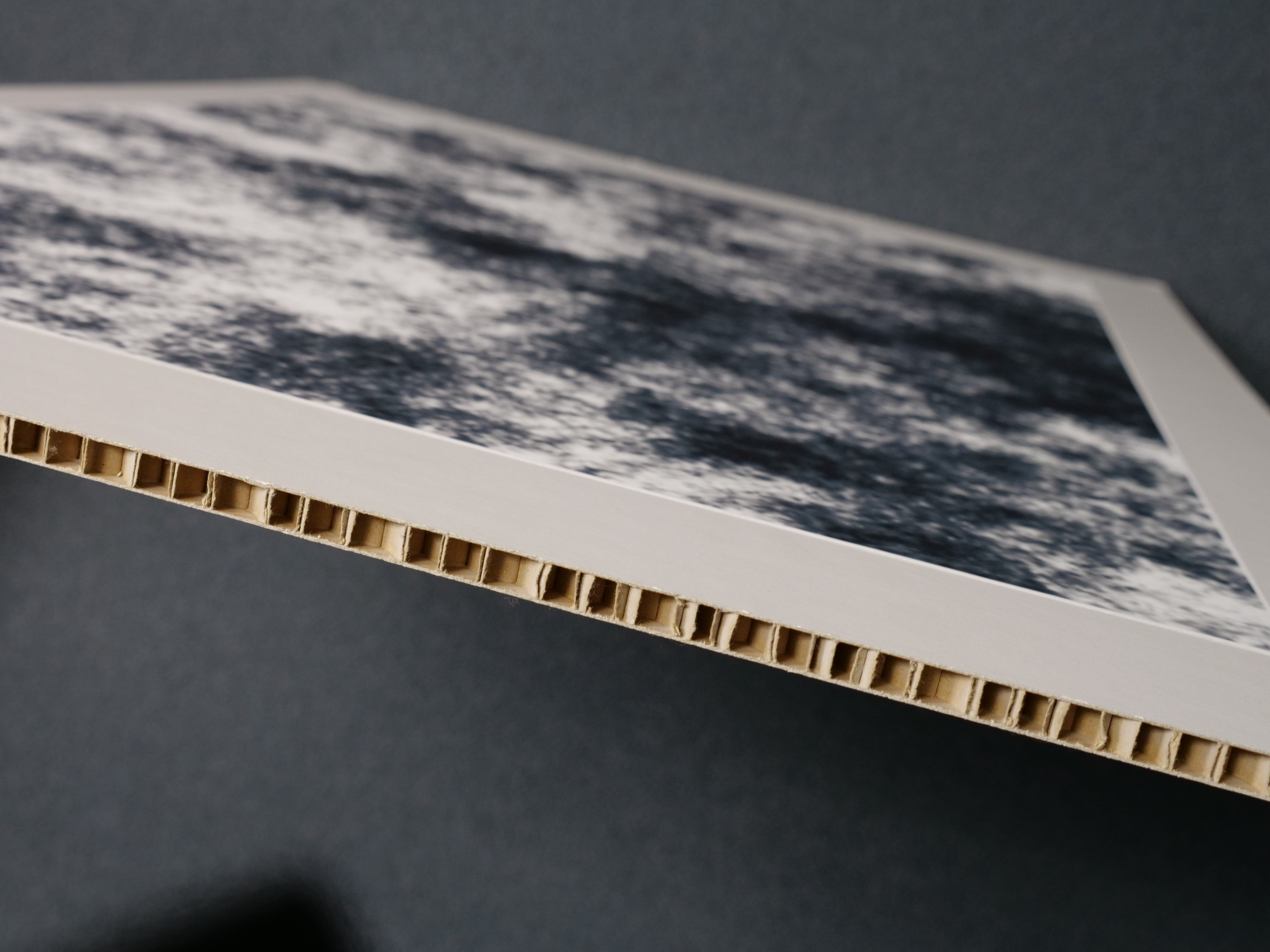
The default calibration image needs to be printed on A1 sized paper, and affixed to a sturdy backing of thick cardboard or foam. Wood or plexiglas can also function as a backing as long as it is thick enough to not bend under weight, that that it is a flat surface.
Any errors on the flatness of the surface will be transferred as error to the calibration. Typically, one should convert the image to a PDF file so that it is resizeable without any distortion. You can mount the image using a spray glue as adhesive. Afterwards it will look something like the following:
Determining image size
For my setup where the cameras are roughly a meter or two meters away from the object of interest with minimal zoom used in the camera lens, the A1 sized print works well. Obviously, if you change the image, or need a larger/smaller image then printing it onto A1 sized paper doesn’t make sense. The size of the calibration image is determined by the angles your cameras have to each other as well as their distance from the object of interest.
If the cameras are at angles 90 degrees to each other facing outwards, then a large calibration image is needed so that both cameras see a part of the calibration image at the same time. Some experimentation may be needed to find the right size for your setup.
Regenerating calibration image
Reasons for re-generating this file could be that the resolution of the cameras is so good and the cameras as far enough apart that one needs a larger image with better resolution, or a similarly sized image with better resolution.
This new image can be generated very easily. Just replace the default file mentioned previously with this new image and it will be used by the system. However, note that the higher the image resolution the longer the time for calibration to finish.
example_ccalib_random_pattern_generator

 This is a sample for generating a random pattern that can be used for calibration.
Usage: random_patterng_generator
    -iw <image_width> # the width of pattern image
    -ih <image_height> # the height of pattern image
    filename # the filename for pattern image


 example command line for generating a random pattern.
   example_ccalib_random_pattern_generator -iw 600 -ih 850 pattern.png
Note: This command should be run from within the docker container, if docker is being used.
Calibrating the cameras
This code uses the open source code of Li, Heng, Köser, Pollefeys which is included in the OpenCV add-on modules.
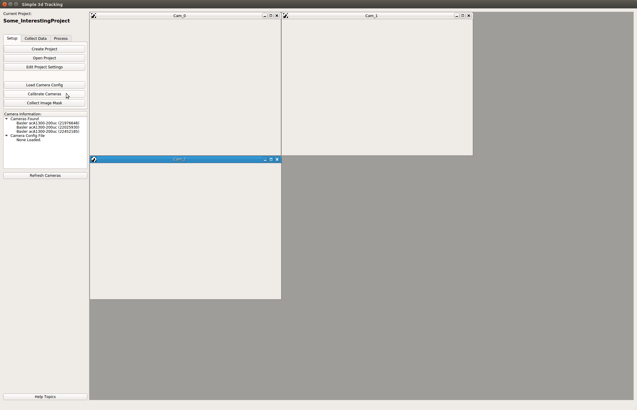
You’ll find the button for calibrating the cameras in the setup tab of the main SnakeStrike window.
Recording the calibration images
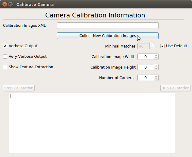
Before one can calibrate the cameras, images need to be collected. Click the buttton for collecting new images. This will bring up a recording dialog. Taking a lot of calibration images just increases the time needed to complete the calibration.
In my setup I use a camera speed of 4 Hz for calibration. With 4 or 5 cameras, 50 images is usually more than enough to get a good calibration.
Moving the calibration image through the viewable space
Every setup will be different, so there isn’t a perfect description of how to move the calibration image through the capture space so that a perfect calibration with result. However, there are a few general guidelines that can help increase the likelihood of a good calibration.
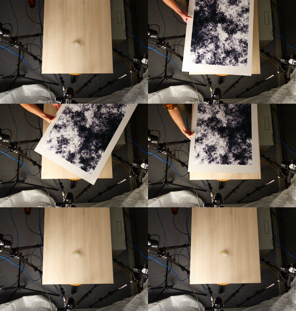
As you can see in the GIF, keep the board moving the whole time to prevent multiple images of the same exact position. Furthermore, it is good to turn the calibration image such that cameras have more oblique view of the image. This is very helpful for distorting the images as well as making sure that the image is viewable by many cameras at the same time.
Running the calibration algorithm
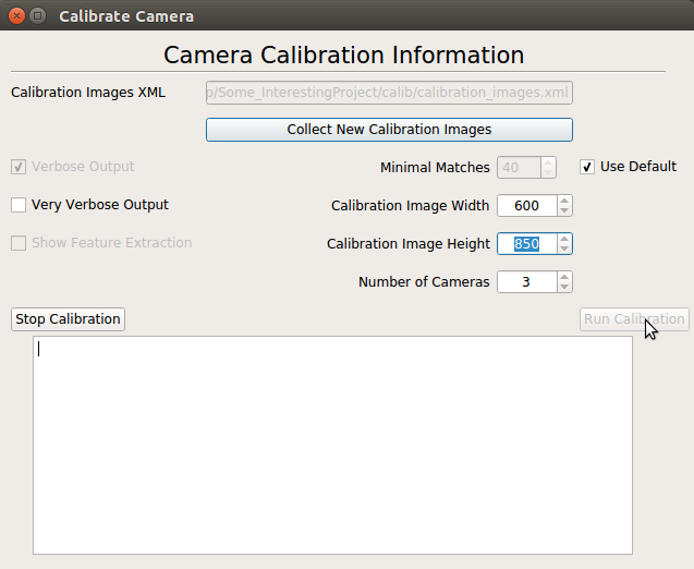
The calibration dialog has quite a few default options. These default options are the ones that work well for me and the setups I have tried. They may need to be fine-tuned for your specific setup.
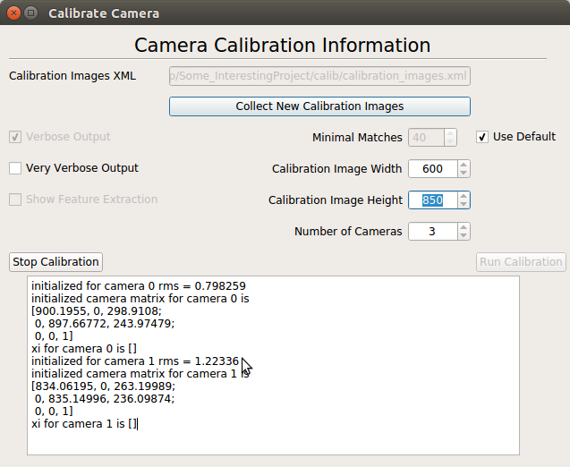
Output of the calibration is sent to the small text window at the bottom of the dialog. You have the option of choosing no output, verbose output, and very verbose output. No output should rarely ever be used as it doesn’t tell you if things were successful or not.
The default of verbose output is a good comprimise between seeing enought information to know if the calibration was good or not, and not having to sift through lots of info. The very verbose output is essentially all of the output of the algorithm. It is the most descriptive, but also a lot more work to sort through.
Once you’ve seen a good exit code on the calibration routine, and the error for the intrinsic matrices as well as the extrinsic matrices is good. Then you can continue on to collecting your actual experiment data.
For me, typically an intrinsic matrix error of less than 1.5 for each camera and an extrinsic error less than 1 or in the low digits is good.
Deciphering calibration output
initialized for camera 0 rms = 0.646547
initialized camera matrix for camera 0 is
[820.97058, 0, 312.94299;
 0, 821.02832, 228.02991;
 0, 0, 1]
xi for camera 0 is []
initialized for camera 1 rms = 0.842932
initialized camera matrix for camera 1 is
[992.71967, 0, 342.71057;
 0, 992.55219, 253.78484;
 0, 0, 1]
xi for camera 1 is []
initialized for camera 2 rms = 0.615072
initialized camera matrix for camera 2 is
[798.37347, 0, 340.02979;
 0, 799.45941, 236.36484;
 0, 0, 1]
xi for camera 2 is []
initial pose for camera 1 is
[0.99544066, 0.0047723539, 0.095263258, -283.03537;
 -0.0036019497, 0.99991584, -0.012453869, 12.687775;
 -0.095314674, 0.012053967, 0.99537426, 48.50708;
 0, 0, 0, 1]
initial pose for camera 2 is
[0.93252403, -0.12041766, 0.34043875, -591.93713;
 0.12327647, 0.99228311, 0.013306826, -48.852966;
 -0.339414, 0.02955915, 0.94017261, 87.973877;
 0, 0, 0, 1]
final camera pose of camera 1 is
[0.99587017, 0.0040811524, 0.09069676, -277.7547;
 -0.0036230993, 0.99997985, -0.0052144467, 3.9452648;
 -0.090716213, 0.0048643085, 0.99586493, 45.158512;
 0, 0, 0, 1]
final camera pose of camera 2 is
[0.93595433, -0.12202941, 0.33030033, -580.44202;
 0.12427015, 0.99214381, 0.01440971, -50.285221;
 -0.32946384, 0.027559642, 0.94376588, 82.39682;
 0, 0, 0, 1]
The camera extrinsics were calculated with an error of 0.472122

Calibration Finished with exit code 0.
Here is the output of running the calibration with verbose output. You can see the camera intrinsic calibration error by looking for lines like
initialized for camera 0 rms
The extrinsic calibration error for all cameras is on the line:
The camera extrinsics were calculated with an error of 0.472122
You can also see the intrinsic matrices for each camera as well as the final pose matrix for each camera relative to camera 0 which is set as the origin.
If you were to select the “very verbose output” option, then the output would look similar to the following excerpt:
open image calib/cam1/1-42.png successfully

number of matched points 176

number of filtered points 102

open image calib/cam1/1-46.png successfully

number of matched points 96

number of filtered points 34
image calib/cam1/1-46.png has too few matched points

open image calib/cam1/1-27.png successfully

number of matched points 140

number of filtered points 68

initialized for camera 1 rms = 0.842932
initialized camera matrix for camera 1 is
[992.71967, 0, 342.71057;
 0, 992.55219, 253.78484;
 0, 0, 1]
In this snippet, one can see what sort of extra information is available with the aforementioned option. The number of filtered points has to be greater than or equal to the minimal matches integer value. The higher this value is the more selective the algorithm is when selecting good calibration images to use in its algorithm.
Selecting too low of value increases the number of images that are used to calibrate the cameras, but can increase the error of the calibration. If the calibration is failing, it can be helpful to look at this output to see if one camera isn’t getting enough good images used in the final calibration.
Calibration is successful
When the calibration is successful it creates a file in the project directory with the intrinsic and extrinsic matrices information. Once a calibration file exists, then recording tab becomes available.
Once this file is available the record button on the “Collect Data” tab becomes enabled.
